Mechanical Design 101
  • BLOG
  • VIDEOS
  • SHOP
    • Specialty items
    • Books
    • Mobile Apps
    • Software
  • RESOURCES
    • MACHINE DESIGN
    • LINKAGE DESIGNS
    • ENERGY AND ENVIRONMENT
    • DESIGN INNOVATION
    • ROBOTICS
    • Smitty and the Professor
    • Lecture Notes
    • CREATIVE
    • Need Help?
    • Uncategorized
  • ABOUT
    • Need Help?
  • Click to open the search input field Click to open the search input field Search
  • Menu Menu
  • Shopping Cart Shopping Cart
    0Shopping Cart
Butterfly drawing mechanism

Design of Drawing Mechanisms

October 20, 2016/by Prof. McCarthy

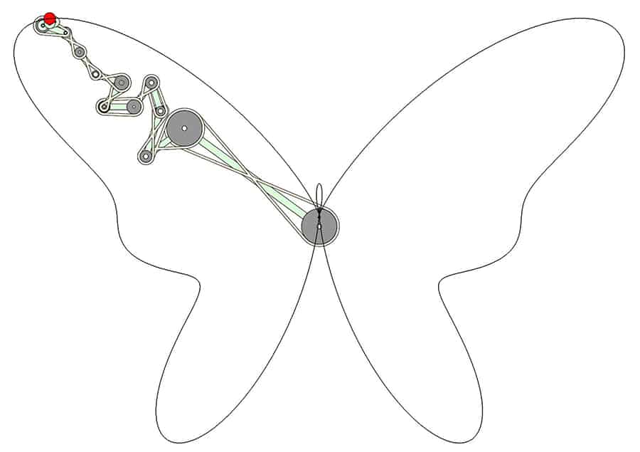
Mechanical systems that draw trigonometric curves provide a versatile way to draw complex curves. Yang Liu designed this serial chain consisting of 14 links coupled by a belt drive to draw the Butterfly curve.


The Butterfly curve is an example of a trigonometric plane curve, and our study of Kempe’s design of linkages to draw algebraic curves has lead us to a way to design serial chains that draw these curves.

Here is how it is done.

Butterfly curve

Butterfly curve

Trigonometric curves. A trigonometric plane curve is a parametrized curve with coordinate functions, P = (x, y), that are finite Fourier series,

Trigonmetric equation

Trigonmetric equation

where ak , bk , ck and dk are real coefficients and theta ranges from 0 to $latex 2\pi$.

A large number of well-known curves have this form, such as Limacon of Pascal, the Cardioid, Trifolium, Hypocycloid and Lissajous figures.

A coupled serial chain. Without going into too much detail, it is possible to use the coefficients ak , bk, ck and dk to define the link dimensions,
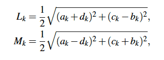
Link dimensions

Link dimensions

and the initial angles,

Initial angles

Initial angles

These parameters allow us to redefine the trigonometric equations of the curve as the coordinate equations of the links of a serial chain,

Serial chain equations

Serial chain equations

This equation identifies the curve as the end of a serial chain consisting of a sequence of links L1, M1, L2, M2 and so on, such that the Lk links rotate counter clockwise and the Mk links rotate clockwise both at the rate $latex k\theta$.

The initial angles define the configuration of the serial chain when  $latex \theta=0$.

The Butterfly drawing mechanism. The trigonometric curve of the Butterfly linkage is defined by the coefficients in the following table,
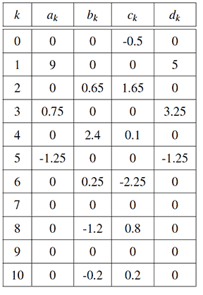
Table of Butterfly coefficients

Table of Butterfly coefficients

These coefficients are used to calculate the dimensions and initial configuration of the serial chain listed in the following table,
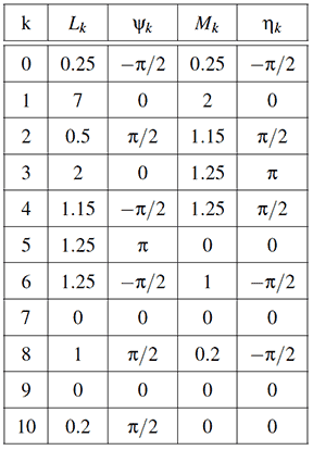
Table of Butterfly link dimensions

Table of Butterfly link dimensions

The result is a serial chain consisting of 14 links that are coordinated to move together as the base rotates. The end-point of the chain draws the Butterfly curve.

Butterfly drawing mechanism

Butterfly drawing mechanism

Tags: design innovation, linkage animations
Share this entry
  • Share on Facebook
  • Share on X
  • Share on Pinterest
  • Share on LinkedIn
  • Share on Tumblr
  • Share on Vk
  • Share on Reddit
  • Share by Mail
https://mechanicaldesign101.com/wp-content/uploads/2016/10/ButterflyMech2.jpg 635 900 Prof. McCarthy https://mechanicaldesign101.com/wp-content/uploads/2016/07/mechanical-design-101LOGOf.png Prof. McCarthy2016-10-20 18:06:162022-07-08 19:36:01Design of Drawing Mechanisms
You might also like
Heart Linkage Heart Trajectory
Leg Mechanisms Walking Machines
DNA origami mechanisms, Advances in Reconfigurable Mechanisms and Robots, Springer 2012 DNA Origami Mechanisms and Machines
MechGen on iPhone MechGen FG is on the iPhone
MK1 Schematic MK.1 Mechanical Computer
Rectilinear Eight-bar Rectilinear eight-bar linkage

Search

Search Search

Recent Blog Posts

  • Innovative Car Door Linkage
  • Spherical Linkage Opening a Jewelry Box
  • Red Lines, Part 6
  • Red Lines, Part 5
  • Red Lines, Part 4
  • Exponential Threat, Part 4
  • Exponential Threat, Part 3
  • Red Lines, Part 3
  • ZotSun: UCI Entry in the Formula Sun Grand Prix
  • UCI Anteater Baja Racing: Five Months to the Competition

Post Categories

  • Automotive Information
  • Bored Robot
  • Chop wood carry water
  • Commentary
  • Creative
  • Design Innovation
  • Energy and Environment
  • Engineering Data
  • Fabrication
  • Give Me Space
  • Kinematic Synthesis
  • Kinematics
  • Lecture Notes
  • Linkage Animations
  • Racecar Engineering
  • Red Lines
  • Robotics Information
  • Smitty and the Professor
  • Student Projects
  • Superluminal
  • UCI Energy Invitational
  • Uncategorized

Events Calendar

October 2016
S M T W T F S
 1
2345678
9101112131415
16171819202122
23242526272829
3031  
« Aug   Nov »

Project-based Learning (links)

  • Energy Invitational
  • Performance Engineering
  • Smitty and the Professor
  • The California Challenge
  • Theoretical Kinematics
© Copyright - Mechanical Design 101
Web Design by Lucky 19
  • Link to Facebook
Link to: 2016 Mechanisms and Robotics Conference Link to: 2016 Mechanisms and Robotics Conference 2016 Mechanisms and Robotics ConferenceMechanisms and Robotics Conference Link to: Robot Ethics Link to: Robot Ethics Robotics HandbookRobot Ethics
Scroll to top Scroll to top Scroll to top