
Mechanical Design 101
  • BLOG
  • VIDEOS
  • SHOP
    • Specialty items
    • Books
    • Mobile Apps
    • Software
  • RESOURCES
    • MACHINE DESIGN
    • LINKAGE DESIGNS
    • ENERGY AND ENVIRONMENT
    • DESIGN INNOVATION
    • ROBOTICS
    • Smitty and the Professor
    • Lecture Notes
    • CREATIVE
    • Need Help?
    • Uncategorized
  • ABOUT
    • Need Help?
  • Click to open the search input field Click to open the search input field Search
  • Menu Menu
  • Shopping Cart Shopping Cart
    0Shopping Cart
Removing Redundant ConstraintsMDA Press

How to Fix SW Motion Analysis Error: Too Many Redundant Constraints

July 19, 2020/by Prof. McCarthy

Kevin Chen,  J. Michael McCarthy,  Shaun Bentley

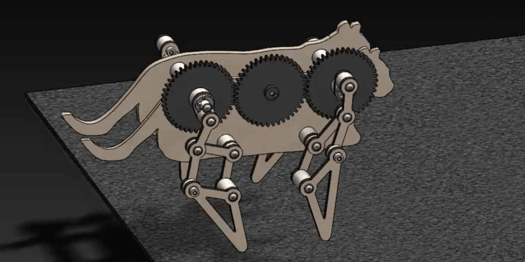
The design and assembly of our four-legged mechanical walkers can yield single degree-of-freedom systems with so many redundant mates that it stalls SolidWorks’ Motion Analysis.  For example, the walker shown in Figure 1 had 782 redundant mates.   The procedure outlined below reduced the number of redundant mates to 114, and Motion Analysis executed efficiently.
Four-legged Walker Assembly
Figure 1.  A four-legged mechanical walker consisting of a body, drive train, and four-leg mechanisms.

Our walker consists of a body, drive train, and four legs.  The legs mechanisms are identical but assembled as front-to-back mirror images.  The component parts of this walker mates were assembled using mates to align and coordinate various subassemblies, resulting in a large number of redundant mates.

In order to reduce the number of redundant mates, we dissolve the subassemblies, combine rigid elements, and mate new subassemblies as follows.

Step 1

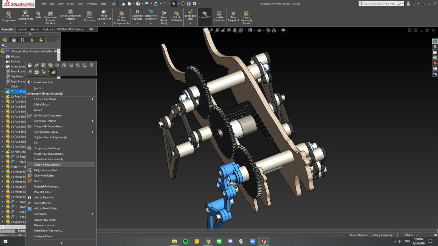
Dissolve all of the subassemblies in the walker. To do this, hover over each assembly and select the menu item Dissolve Assembly. See Figure 1.
New Sub Assemblies
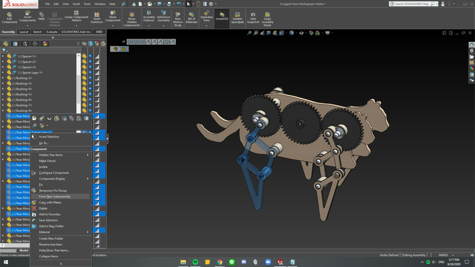
Figure 2.  Selected parts for new subassembly.

Step 2

Form new subassemblies for each leg, the drive train, and the body. See Figure 2. To do this, first, hover over the part, press “tab” to hide the part in order to identify it easily; and then, select all of the hidden parts, and right-click to open menu and select Form New Subassembly.
Form New Assemblies
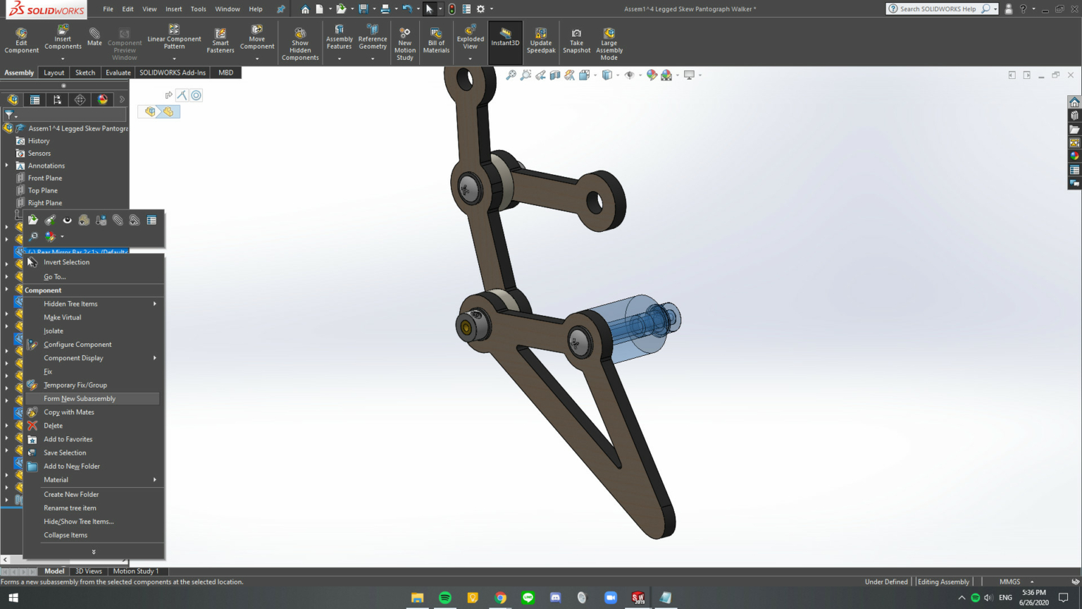
Figure 3.  Within each new subassembly form subassemblies of parts that do not move relative to each other.

Step 3

Within each new subassembly combine parts that do not move relative to each other.  See Figure 3. The tree structure should consist of separate assemblies of rigid elements with the remaining mates between the assemblies. See Figure 4. 
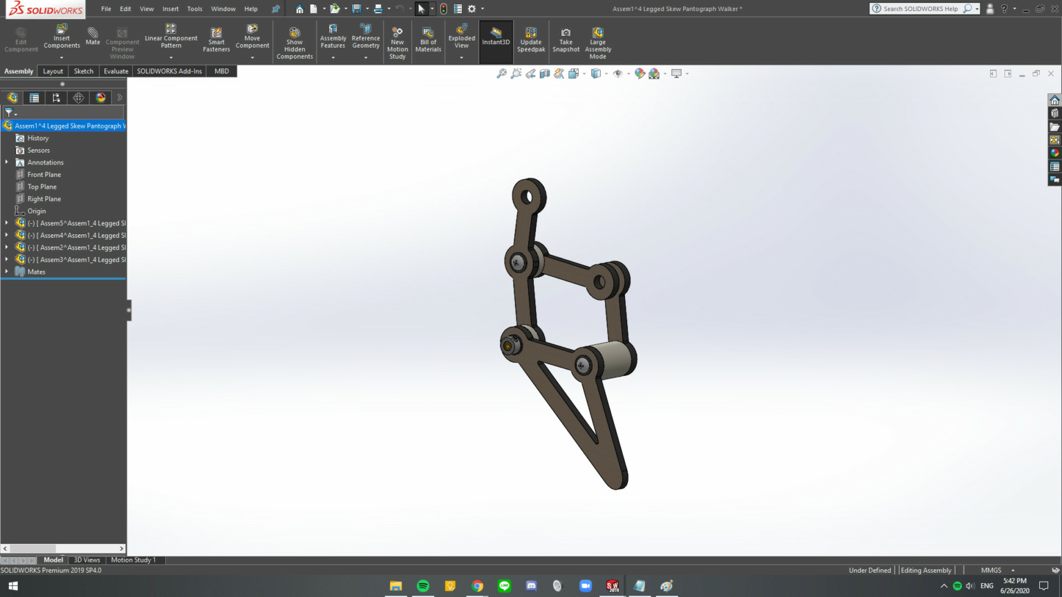
Rigid Elements
 Figure 4.  The assembly should consist of subassemblies that move as rigid elements relative to each other.

Step 4

 Repeat Step 3 for all of the new subassemblies.  The result is shown in Figure 5.
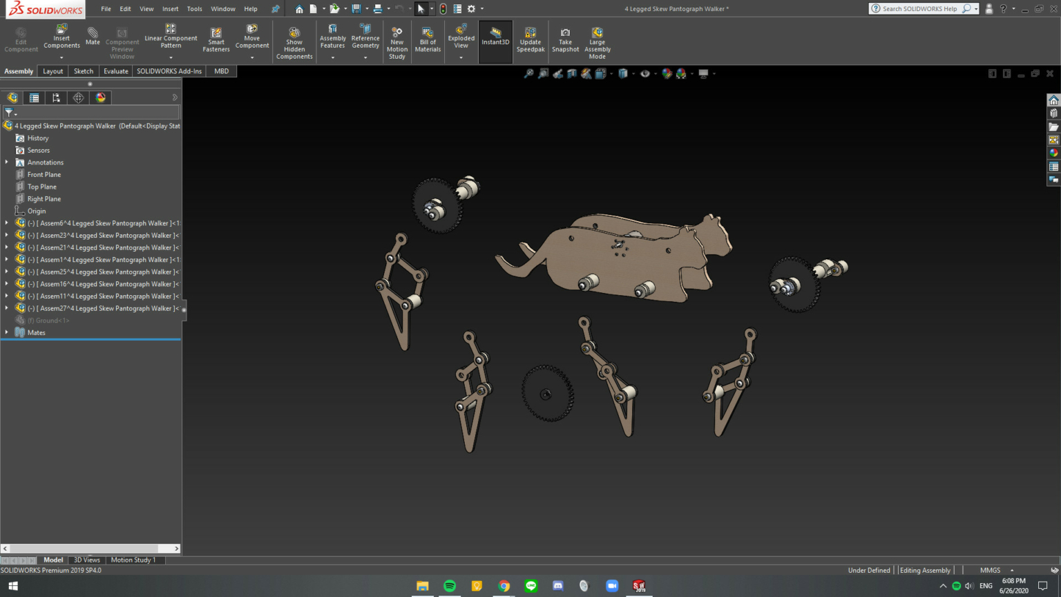
Rigid subassemblies
 Figure 5.  The subassemblies that define the mechanical walker.  Notice that the tree structure consists of subassemblies and no individual parts.

Step 5

Delete the mates in the main assembly.  Introduce the mates required for movement using hinge mates, rather than coincident or concentric mates, where possible.

Step 6

Make the subassemblies at the top-level flexible.  Right-click on the assembly and select the flexible assembly icon  pastedGraphic.png.

The result of this procedure is a system with 114 redundant mates that Motion Analysis can process effectively.  The result is that animation shown below.

Share this entry
  • Share on Facebook
  • Share on X
  • Share on Pinterest
  • Share on LinkedIn
  • Share on Tumblr
  • Share on Vk
  • Share on Reddit
  • Share by Mail
https://mechanicaldesign101.com/wp-content/uploads/2020/07/Screen-Shot-2020-07-19-at-5.12.37-PM.png 992 1986 Prof. McCarthy https://mechanicaldesign101.com/wp-content/uploads/2016/07/mechanical-design-101LOGOf.png Prof. McCarthy2020-07-19 17:15:522020-07-19 17:39:58How to Fix SW Motion Analysis Error: Too Many Redundant Constraints

Search

Search Search

Recent Blog Posts

  • Innovative Car Door Linkage
  • Spherical Linkage Opening a Jewelry Box
  • Red Lines, Part 6
  • Red Lines, Part 5
  • Red Lines, Part 4
  • Exponential Threat, Part 4
  • Exponential Threat, Part 3
  • Red Lines, Part 3
  • ZotSun: UCI Entry in the Formula Sun Grand Prix
  • UCI Anteater Baja Racing: Five Months to the Competition

Post Categories

  • Automotive Information
  • Bored Robot
  • Chop wood carry water
  • Commentary
  • Creative
  • Design Innovation
  • Energy and Environment
  • Engineering Data
  • Fabrication
  • Give Me Space
  • Kinematic Synthesis
  • Kinematics
  • Lecture Notes
  • Linkage Animations
  • Racecar Engineering
  • Red Lines
  • Robotics Information
  • Smitty and the Professor
  • Student Projects
  • Superluminal
  • UCI Energy Invitational
  • Uncategorized

Events Calendar

July 2020
S M T W T F S
 1234
567891011
12131415161718
19202122232425
262728293031  
« Jun   Oct »

Project-based Learning (links)

  • Energy Invitational
  • Performance Engineering
  • Smitty and the Professor
  • The California Challenge
  • Theoretical Kinematics
© Copyright - Mechanical Design 101
Web Design by Lucky 19
  • Link to Facebook
Link to: The Design of Mechanical Walkers: Spring 2020 Student Projects Link to: The Design of Mechanical Walkers: Spring 2020 Student Projects The Design of Mechanical Walkers: Spring 2020 Student ProjectsSix-Legged Mechanical WalkerMDA Link to: The Bored Robot: Controlling Two Drive Motors for a Walking Machine Link to: The Bored Robot: Controlling Two Drive Motors for a Walking Machine The Bored RobotMDAThe Bored Robot: Controlling Two Drive Motors for a Walking Machine
Scroll to top Scroll to top Scroll to top