
Five Position Synthesis of Four-bar Function Generators
Our MechGen FG iOS application provides five position synthesis for four-bar linkages. A Demo of the iPad version is provided here. It is also available on the iPhone.
View Post
Our MechGen FG iOS application provides five position synthesis for four-bar linkages. A Demo of the iPad version is provided here. It is also available on the iPhone.
View Post
The graphical construction of a four-bar linkage that coordinates two positions of an input crank with two positions of an output crank is presented in this video using Geogebra.
A linkage that coordinates the values of input and output angles is called a function generator. It is possible to design a four-bar linkage to coordinate as many as five input and output angles. However, this requires numerical calculations using software such as our MechGen FG iOS application.
More notes on Kinematic Synthesis Also see my book Kinematic Synthesis of Mechanisms: a project based approach
View Post
This video adds a skew pantograph to a four-bar linkage in order to reorient and change the size of the coupler curve. The result is a six-bar leg mechanism with a foot trajectory that is a scaled version of the original coupler curve.
View Post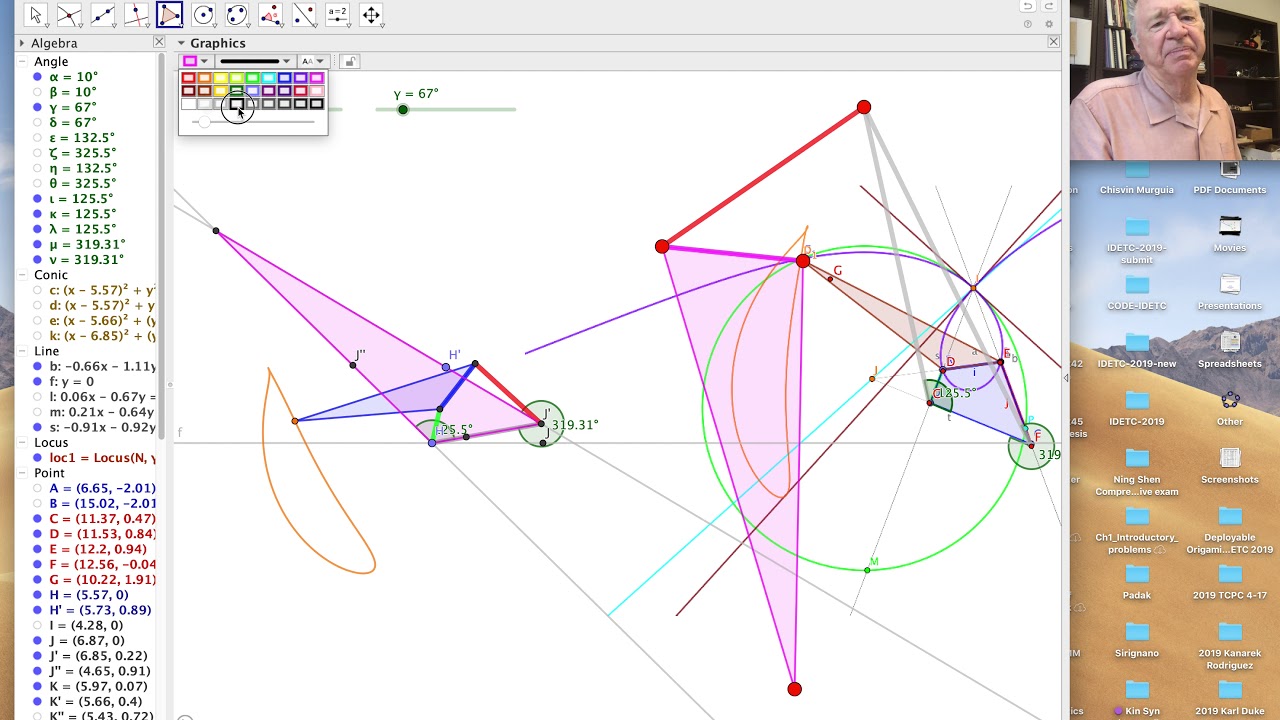
In this video, we start with a four-bar linkage and coupler curve and construct an additional crank with a floating link connected to the coupler point. This floating link becomes the leg of the Klann-style leg mechanism. Adjustment of the dimensions of the added links shapes the foot trajectory.
View Post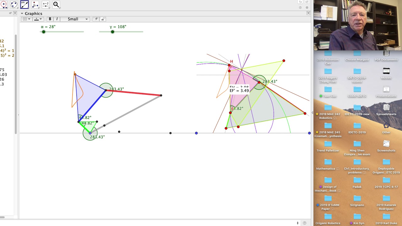
This video starts with a four-bar linkage with a coupler curve that is to be used as the foot trajectory for a leg mechanism. It presents a Geogebra construction of two additional bars, one of which is connected to the coupler point and moves without rotating. This means the bar can be expanded into a leg that places the desired coupler curve where the designer specifies. This is described in Chapter 4 of Kinematic Synthesis of Mechanism.
View Post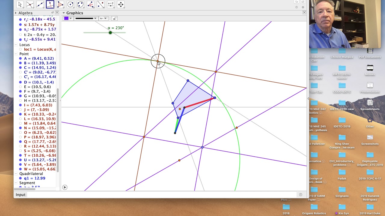
This video shows the construction of the cubic of stationary curvature. The intersection of the cubic of stationary curvature with the inflection circle, iw Ball’s point which is a coupler point that traces a locally straight line trajectory.
This video also shows how to vary the coupler point and the dimensions of the reference polygon for the four-bar linkage to vary the shape of the coupler curve.
View Post
This tutorial constructs the inflection circle for a particular configuration of a four-bar linkage. This construction was recommended by my colleague Gordon Pennock because it is simpler than the one I provide in my book Kinematic Synthesis of Mechanisms.
View Post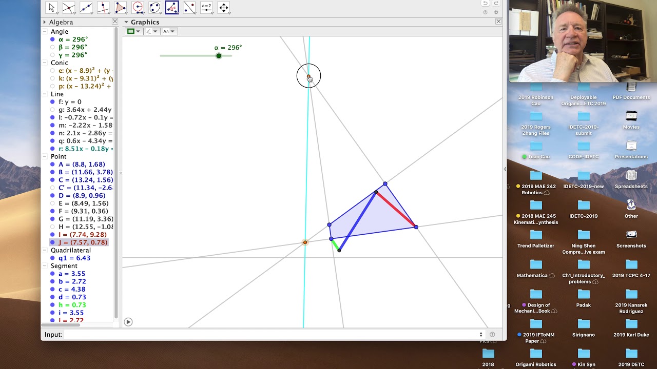
This tutorial shows how to use Geogebra to construct the canonical coordinate system for a particular configuration of a four-bar linkage.
It starts with a quadrilateral which is to be the configuration of the linkage at a particular instant. Then constructs the velocity pole and the instant center of the positions of the input and output cranks. Connecting these lines defines the collineation axis.
Bobillier’s theorem completes the construction by defining the tangent to the moving centrode.
View Post
Our Sphinx software was the first computer-aided design system for spherical linkages. It used IRIS system by Silicon Graphics. Collaboration with Judy Vance lead to a Virtual Reality version of this design system.
This is a link to the description of this research at Iowa State University.
This video shows the operation of these two design systems;
View Post
My first experience with computer based kinematic synthesis was a 1982 presentation by Roger Kaufman of his KinSyn linkage design software on an Apple II microcomputer. This is a link to his description of his experience in those early days of computer-aided design of linkages.
His paper that describes this software can be found here. The photos are a terrific look into the computer technology in the 1970’s.
Here is a video that describes the operation of KinSyn, which I find to be an impressive integration of kinematics calculations in the background with a useful graphical presentation of information to the designer. I have to say that the graphical display was impressive in its day.
View Post