https://mechanicaldesign101.com/wp-content/uploads/2020/07/Screen-Shot-2020-07-19-at-5.24.54-PM.png8321206Prof. McCarthyhttps://mechanicaldesign101.com/wp-content/uploads/2016/07/mechanical-design-101LOGOf.pngProf. McCarthy2020-07-19 17:31:112020-07-19 17:33:27The Bored Robot: Controlling Two Drive Motors for a Walking Machine
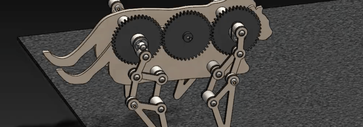
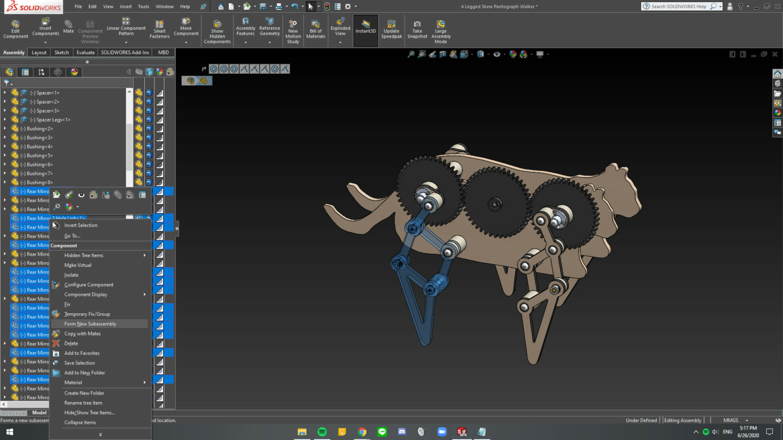
The design and assembly of our four-legged mechanical walkers can yield single degree-of-freedom systems with so many redundant mates that it stalls SolidWorks’ Motion Analysis. For example, the walker shown in Figure 1 had 782 redundant mates. The procedure outlined below reduced the number of redundant mates to 114, and Motion Analysis executed efficiently.
Figure 1. A four-legged mechanical walker consisting of a body, drive train, and four-leg mechanisms.
Our walker consists of a body, drive train, and four legs. The legs mechanisms are identical but assembled as front-to-back mirror images. The component parts of this walker mates were assembled using mates to align and coordinate various subassemblies, resulting in a large number of redundant mates.
In order to reduce the number of redundant mates, we dissolve the subassemblies, combine rigid elements, and mate new subassemblies as follows.
Step 1
Dissolve all of the subassemblies in the walker. To do this, hover over each assembly and select the menu item Dissolve Assembly. See Figure 1.
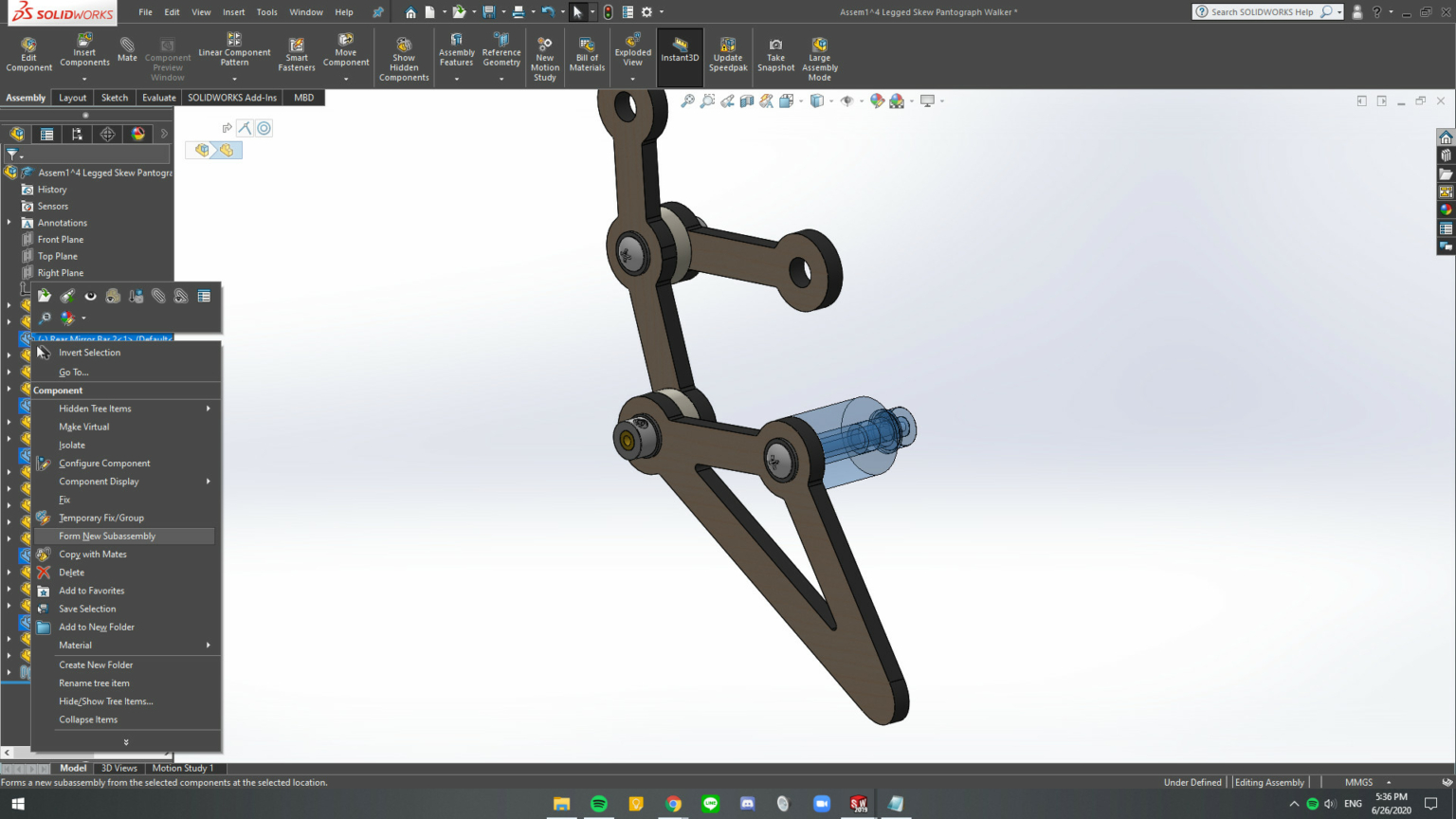
Figure 2. Selected parts for new subassembly.
Step 2
Form new subassemblies for each leg, the drive train, and the body. See Figure 2. To do this, first, hover over the part, press “tab” to hide the part in order to identify it easily; and then, select all of the hidden parts, and right-click to open menu and select Form New Subassembly.
Figure 3. Within each new subassembly form subassemblies of parts that do not move relative to each other.
Step 3
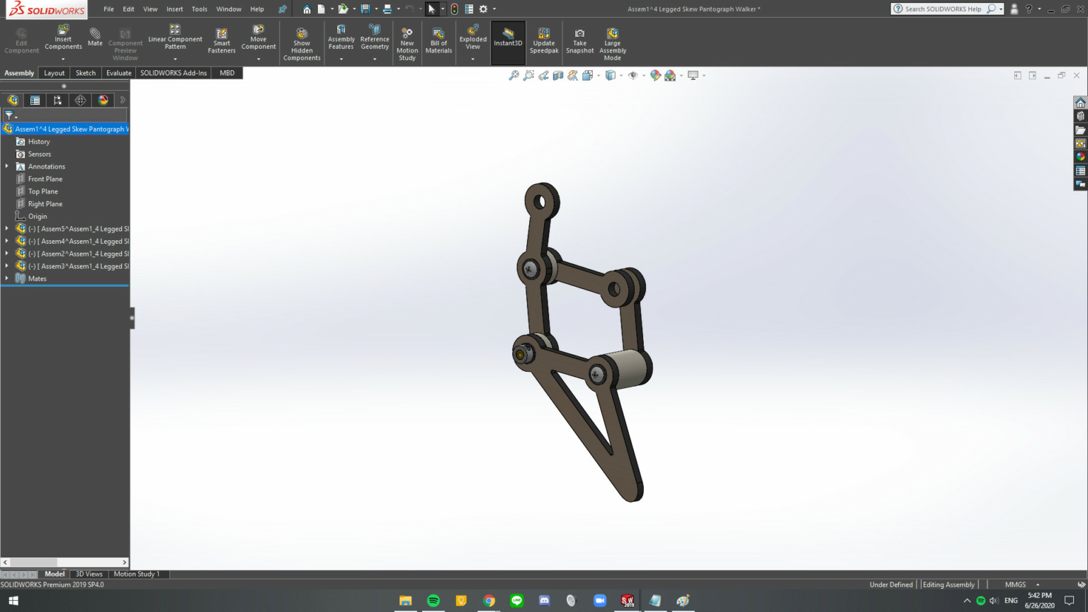
Within each new subassembly combine parts that do not move relative to each other. See Figure 3. The tree structure should consist of separate assemblies of rigid elements with the remaining mates between the assemblies. See Figure 4.
Figure 4. The assembly should consist of subassemblies that move as rigid elements relative to each other.
Step 4
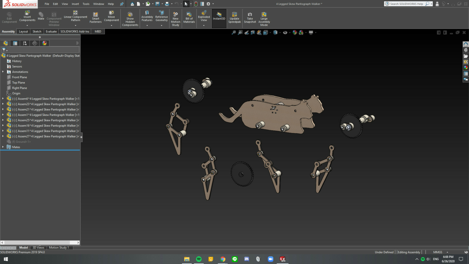
Repeat Step 3 for all of the new subassemblies. The result is shown in Figure 5.
Figure 5. The subassemblies that define the mechanical walker. Notice that the tree structure consists of subassemblies and no individual parts.
Step 5
Delete the mates in the main assembly. Introduce the mates required for movement using hinge mates, rather than coincident or concentric mates, where possible.
Step 6
Make the subassemblies at the top-level flexible. Right-click on the assembly and select the flexible assembly icon .
The result of this procedure is a system with 114 redundant mates that Motion Analysis can process effectively. The result is that animation shown below.
https://mechanicaldesign101.com/wp-content/uploads/2020/07/Screen-Shot-2020-07-19-at-5.12.37-PM.png7991600Prof. McCarthyhttps://mechanicaldesign101.com/wp-content/uploads/2016/07/mechanical-design-101LOGOf.pngProf. McCarthy2020-07-19 17:15:522020-07-19 17:39:58How to Fix SW Motion Analysis Error: Too Many Redundant Constraints
Specify three positions for the foot of a leg consisting of a hip and knee joint;
Use three position synthesis to design a four-bar function generator to guide the hip joint;
Then use three position synthesis to design a second four-bar function generator to guide the knee joint;
And finally assemble the linkage to determine the trajectory of the foot. Adjusting the lengths of the leg segments, the position of the hip, the specified positions of the input cranks, and the position of the coupler attachments to the input cranks vary the resulting foot trajectory. An example leg mechanism is shown at the end of this video.
Part 1:4 Setting up the design
Part 2:4 Synthesis of the hip function generator.
Part 3:4 Synthesis of the knee function generator.
Part 4:4 Assembly of the leg mechanism, exploration of design variations, and an example final leg design.
https://mechanicaldesign101.com/wp-content/uploads/2019/05/Screen-Shot-2019-05-23-at-4.16.12-PM.png10411600Prof. McCarthyhttps://mechanicaldesign101.com/wp-content/uploads/2016/07/mechanical-design-101LOGOf.pngProf. McCarthy2019-05-23 16:27:142019-05-25 12:37:37Construction of a Leg Mechanism
Prof Haijun Su at Ohio State University had his students design walking machines for their final project in ME 5751. Here are videos of four project teams from that event.
Team A:
Team B:
Team C:
Team D:
https://mechanicaldesign101.com/wp-content/uploads/2019/04/Screen-Shot-2019-04-16-at-2.20.21-PM.jpg7401304Prof. McCarthyhttps://mechanicaldesign101.com/wp-content/uploads/2016/07/mechanical-design-101LOGOf.pngProf. McCarthy2019-04-16 14:22:582019-05-25 12:08:24Walking Machine Class Projects: Ohio State ME 5751
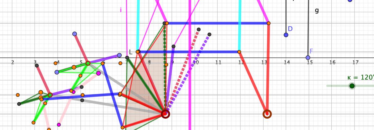
This is a Geogebra animation of the leg mechanism for the Strider walker. It is a symmetrical design that allows the formation of a second foot assembly by simply adding two more bars.
Strider leg mechanism.
This is an animation of the leg mechanism in the TrotBot walker.
TrotBot leg mechanism.
https://mechanicaldesign101.com/wp-content/uploads/2019/04/Screen-Shot-2019-04-10-at-10.55.22-AM.png4221600Prof. McCarthyhttps://mechanicaldesign101.com/wp-content/uploads/2016/07/mechanical-design-101LOGOf.pngProf. McCarthy2019-04-10 11:03:032019-05-25 12:13:41Strider and TrotBot at DIYWalkers.com
I am pleased to report that a paperback version my book Introduction to Theoretical Kinematics: the mathematics of movement is on-line with Amazon.com. I have updated it to reflect current terminology in Robotics and to correct all of the errors that I could identify. Please select the link Introduction to Theoretical Kinematics.
https://mechanicaldesign101.com/wp-content/uploads/2018/07/Amazon-ITTK.jpg8001600Prof. McCarthyhttps://mechanicaldesign101.com/wp-content/uploads/2016/07/mechanical-design-101LOGOf.pngProf. McCarthy2018-07-20 13:36:232018-07-20 13:39:16Introduction to Theoretical Kinematics, paperback on Amazon.com
I found this excerpt of the TEDx talk by Bruno Siciliano describing the growing research area of Roboethics to be fascinating and important. Prof. Siciliano is the Director of the ICAROS Center at the Universita degli Studi di Napoli Federico II. He is co-editor with Oussama Khatib of the first and second editions of the Springer Handbook of Robotics. The entire talk is available at the link Robotics and Napoli.
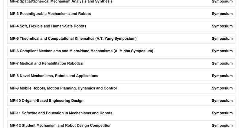
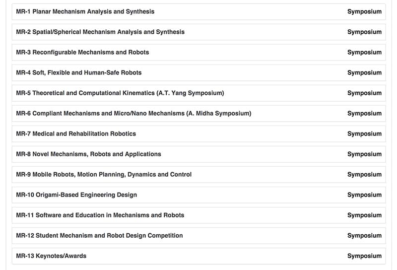
Symposia organized for the 2016 Mechanisms and Robotics Conference
The 2016 Mechanisms and Robotics conference is part of International Design Engineering Technical Conferences organized by ASME International in Charlotte, North Caroline, August 22-24.
For some reason, ASME has broken these links to the 2016 IDETC conference, but you can find out more about each of the symposia at the conference overview link: 2016 ASME Mechanism and Robotics Conference Overview. Then select the Expand all Symposia Link to see the sessions and a list of papers.
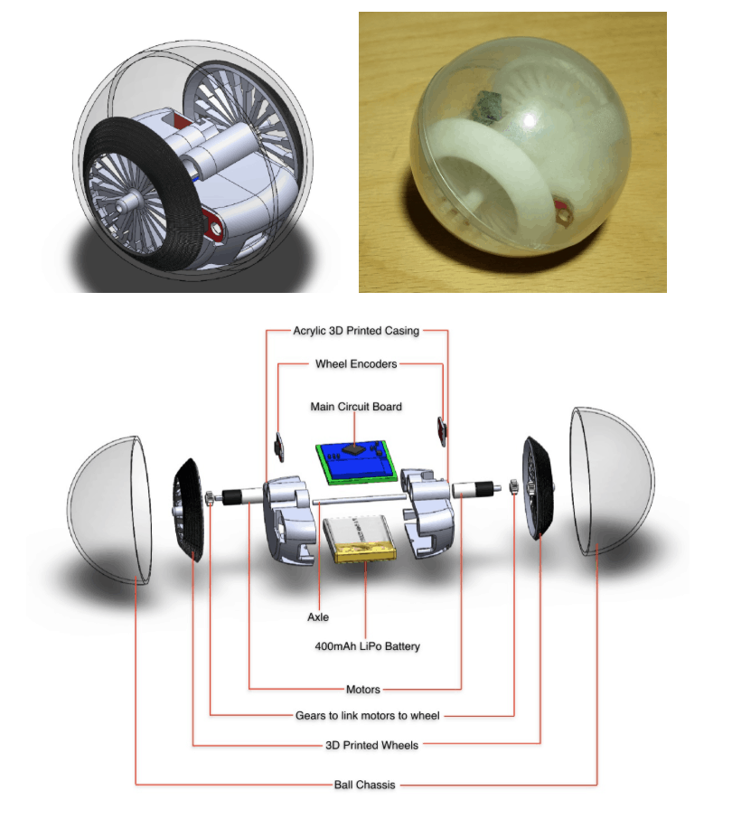
A research team including Profs. GimSong Soh, Kristin Wood and Kevin Otto at Robotics Innovation Lab at the Singapore University of Technology and Design has developed a rolling robot about the size of a baseball. The design and motion planning of this robot, Virgo 2.0, was presented at the Mechanisms and Robotics Conference which was part of the 2015 ASME Design Engineering Technical Conferences, August 2-5, in Boston, MA. A demonstration of the Virgo 2.0 moving through a figure eight path around obstacles is shown in the video below.
https://mechanicaldesign101.com/wp-content/uploads/2015/08/Virgo-2-SUTD.png906810Prof. McCarthyhttps://mechanicaldesign101.com/wp-content/uploads/2016/07/mechanical-design-101LOGOf.pngProf. McCarthy2015-08-11 07:13:422022-09-17 09:28:25Rolling Robot at SUTD

 MDA
MDA
 MDA Press
 JMM
JMM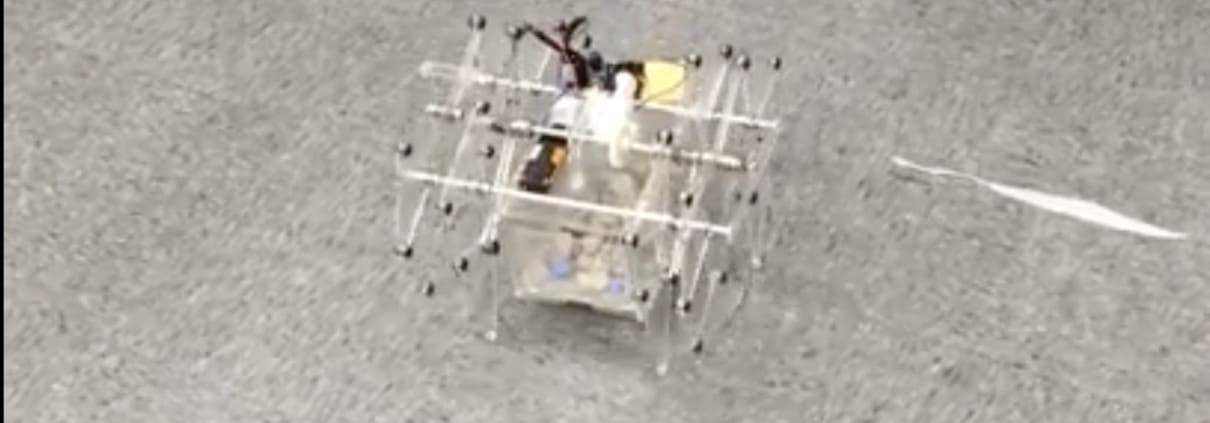


 GraspLab Seminar