Tag Archive for: design innovation

Linkage Patents

Want a patent? Try a Six-bar linkage

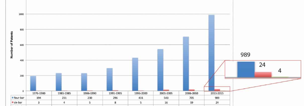
Patents including six-bar linkages are rare. Thousands of U.S. Patents have been awarded over the past forty years that involve four-bar linkages, but less than a hundred involve six-bar linkages, Figure 1.

Linkage Patents

Figure 1.  Since 1976, 3619 patents have been awarded that involve four-bar linkages and only 84 that involve six-bar linkages.

Add two bars to a four-bar to get a six-bar. A four-bar linkage, familiar to all mechanical designers, has an input lever connected by a rod to an output lever, Figure 2 (top). Add two more bars and you have a six-bar linkage. Unfortunately, the standard way to add those bars yields sequence of two four-bar linkages, Figure 2 (bottom), which is not really new. There are other ways to add these two bars but they are beyond the state-of-the-art.

Six-bar Watt 2

Figure 2. Add two bars to a four-bar linkage (top) to obtain a sequence of two four-bar linkages (bottom). This is the best designers can currently do for a six-bar linkage.

Other ways to add two bars. The two additional bars can be added to a four-bar linkage by attaching one end to the connecting rod and the other end to the output link. The result is a stack of two four-bar linkages, known as the Watt I six-bar linkage, Figure 3(a).

Another way is to connect one end of the two bars to the input lever and the other to output lever. This can be done in two ways, either on top of or beneath the four-bar linkage. When added on top, the result is a five-bar loop stacked on the four-bar linkage, known as the Stephenson I six-bar, Figure 3(b). When added beneath, the four-bar linkage is stacked on a five-bar loop, which is a Stephenson II sixbar, Figure 3 (c).

A systematic procedure for design of these alternative six-bar linkages is simply not available to mechanical designers.

Six-bar Chains

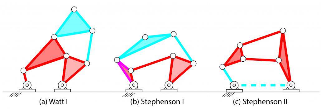
Figure 3. Three ways to add two bars to a four-bar linkage to obtain a six-bar linkage, each of which is beyond the state-of-the-art.

Solving the loop equations for four-bar and six-bar linkages. There is a simple, though mathematical, reason why four-bar linkages are easy to design and six-bar linkages that are more than a sequence of two four-bar linkages are very hard to design.

Almost sixty years ago in 1954, Ferdinand Freudenstein showed that if we define the movement required of a four-bar linkage, then its dimensions can be computed from its loop equations, which in modern form are give by,

Four-bar Loop Equations

Four-bar Loop Equations

He also showed that the solution of these equations is equivalent to finding the roots of a fourth degree polynomial, which is easy to do.

Soon afterward researchers obtained two sets of loop equations for six-bar linkages and showed that for a required movement, the solution of its loop equations,

Six-bar Loop Equations

Six-bar Loop Equations

is equivalent to finding the roots of a polynomial system of degree, d=264×10^6. A complete solution was only recently achieved after 300 hours of computation on a high performance computer cluster.

This stunning increase in complexity gets worse for eight-bar linkages obtained by adding two bars to a six-bar linkage, which yields three sets of loop equations. In this case calculating the dimensions of the linkage involves the solution of a polynomial system estimated to be of degree, d=10^15, which is massively beyond capabilities of even theoretical polynomial solvers.

A four-bar with additional design parameters. Once we understand the structure of the design equations for four-bar, six-bar and even eight-bar linkages, it is possible to take a different approach to the problem of calculating a design from a movement requirement.

A four-bar linkage has eight design variables, which are the four pairs of coordinates that define its hinged joints. Similarly, a six-bar linkage has seven hinged joints or 14 design parameters, and an eight-bar linkage has 10 joints or 20 design parameters. It is possible to consider a six-bar and even an eight-bar linkage as a four-bar linkage with extra design variables. The question then becomes how to use these extra design variables to improve the performance of the linkage system.

Six-bar linkages provide simple and effective movement. But is there ever a situation where the complexity of a six-bar linkage is preferred over a four-bar linkage that provides the same movement? Of course there is, but let’s let design engineers describe their experience.

Søren Matthesen, design engineer for Vendlet Aps, which makes automated equipment for beds, studied the use of gears, guide rails and four-bar linkages and wound up using a six-bar linkage for his application. He states,

“What really mattered to me was the fact that the six-bar linkage enabled me to solve my design task unlike the four-bar linkage. This is a huge advantage in functionality. Compared to my initial solutions, the six-bar linkage system ends up being more simple and stable to produce, use and maintain.”

Mike Sutherland, design engineer, Zennen Engineering, designed a six-bar linkage to fold the rear wheel of a new full-scale folding bicycle, Figure 4. He states,

“The six-bar rearstay folding linkage provided very tight package; that besides being convenient for transportation, also has something of a ‘Transformer’ attraction about it…”

Zennen Folding Bike

Figure 4. The Zennen folding bicycle concept uses a six-bar linkage to fold the full-sized rear wheel against the folded front forks, downtube and seat tube.

The simple answer is that a six-bar linkage designed to achieve the same movement as a four-bar linkage will have free design parameters that allow optimization of other features important to the designer, and this definitely justifies the increase in complexity. And it may be an invention ready for a U. S. Patent.

SIAM News

SIAM News: Biologically inspired linkage design

SIAM News

SIAM News

This article by Jon Hauenstein with me for SIAM News (Society for Industrial and Applied Mathematics) describes research by Mark Plecnik in the computer-aided design of linkages to provide mechanical movement of a bird’s wing. Here is Mark’s video of the his wing flapping mechanism.

Folding Bicycle

Full Size Folding Bicycle

Folding Bicycle

Folding Bicycle

Michael Sutherland and his team at Zennen Engineering designed this full-size folding bicycle that has a dramatically different folding action from current designs.

Zennen Engineering has a new concept that they are kind enough to say was inspired by our UCI Folding Structure. This new design rotates the rear wheel support around the bottom bracket, and folds the front forks against the down tube and seat tube to form a compact package. It is a unique movement.

Jon Stokes, in our Robotics and Automation Lab, helped by adding the four-bar function generator to combine the two folding actions. It is a great concept, and it will be interesting to see if it achieves commercial success.

Montague Bikes provides a popular line folding full sized bicycles, which fold sideways around the seat tube.

Target Profiles for Morphing Linkage

Actuating Morphing Linkages

Target Profiles for Morphing Linkage

Target Profiles for Morphing Linkage

Lawrence Funke and Prof. James Schmiedeler of the University of Notre Dame Locomotion and Biomechanics Lab show that the movement of a morphing linkage through its target profiles can be improved by coordinating actuation of the sub-chains. This was presented at the Mechanisms and Robotics Conference which was part of the 2015 ASME Design Engineering Technical Conferences, August 2-5, in Boston, MA. The video below shows the improvement obtained by moving from 1 to 3 coordinated actuators.

Virgo 2 SUTD

Rolling Robot at SUTD

Virgo 2 SUTD
Virgo 2 SUTD


A research team including Profs. GimSong Soh, Kristin Wood and Kevin Otto at Robotics Innovation Lab at the Singapore University of Technology and Design has developed a rolling robot about the size of a baseball. The design and motion planning of this robot, Virgo 2.0, was presented at the Mechanisms and Robotics Conference which was part of the 2015 ASME Design Engineering Technical Conferences, August 2-5, in Boston, MA. A demonstration of the Virgo 2.0 moving through a figure eight path around obstacles is shown in the video below.

Fourbar Extrusion

A four-bar linkage provides a shape changing extrusion die

Fourbar Extrusion
Fourbar Extrusion

Prof. Andrew Murray and his team at the Design of Innovative Machines Laboratory have developed a dynamic extrusion die that changes shape while in operation. This provides a new capability for rapid manufacture of innovative geometry for metal and plastic bars, channels, hoses, and more. For more information see his laboratory website, University of Dayton DIMLab.

This video provides an extreme introduction to the DIM Lab at the University of Dayton.

MK1 Schematic

MK.1 Mechanical Computer

Nicholas Bodley sent me to www.maritime.org for information about the MK.1 mechanical computer that he used as a Navy Fire Control Technician during the Korean War. Just the schematic of its operation is a dizzying flowchart.

A description of the mechanical components of this computer system can be found in the manual Basic Fire Control Mechanisms (62.7MB). It is an excellent description of the use gears, cams and linkages for computation.

MK 1 Mechanical Computer

MK 1 Mechanical Computer

Bernie Roth

Bernard Roth: The Achievement Habit

The Achievement Habit

The Achievement Habit


I found this book to be remarkable. First, because the initial chapters resonate so clearly with my own experiences over the past 10 years guiding large student teams through project-based learning to complete the design, manufacturing, testing and eventual participation in intercollegiate race car engineering competitions. Initially, I thought what was required was technical expertise so I focussed on preparing the science and technology in an effective way so the students could understand it. Then, it seemed the challenge was poor fabrication skills, so I coordinated specialized training and found advisors to help.

However, I eventually found that the real challenge lay in helping the students to understand how to work together. For example, I now know that every year I must manage the crisis that students experience as they face the enormity of a project that requires that they trust each other. Because students instinctively control everything that impacts their success, they resist collaboration and take on more and more until they are overwhelmed.

This is one of many principles that Bernard Roth presents in the first four chapters, and the one I can rightly say that I stumbled upon myself in 10 years of involvement in project-based learning. So it is satisfying to see his clear explanations and examples of how these principles are critical to project-based engineering education.

But the real reason that I find this book to be remarkable is that the last three chapters anticipate, explain and provide guidance for recent deep concerns that I have regarding the future of my project students. Let me try to explain.

While I know Bernard Roth well, it is primarily as a masterful research scientist, who regularly over the course of his career formulated and solved problems that are now considered to be at the foundation of Robotics theory. I also knew that he was part of a team of faculty who regularly provided creativity workshops around the world, and that this activity evolved into the academic principles that guide the successful Hasso Plattner Institute of Design at Stanford University. Yet, I was never directly involved in one of these workshops, though I can now see that exercises in a design course at Stanford years ago were precursors to what he has refined and presents in this book.

For over 20 years, I taught engineering courses by working diligently to organize the material in what I thought was a clear and compelling way, present it to the students, and engage them with homework and tests to see if they could repeat back to me what I felt was important. As I got better at this, I became more efficient, providing students a complete package of notes, well-design homework exercises, and tests that guided their studies. And they became more efficient as well, providing me what I wanted with minimum effort. However, I began to get the sense that my students did not consider this experience to be any more meaningful than a hazing process for admission to a fraternity.

My intuition was verified dramatically, when I became involved in project-based learning. After almost two years working for a robotics company and experiencing the messy challenge of guiding a team of engineers to a successful product launch, I found that I had little interest in the lecture, homework, and test process. So an unlucky group of students, who were hoping I would just sign their advisor paperwork and leave them alone, found that I wanted to meet with them weekly. I had no idea what they needed, so I lectured to them about the technology of their project and how companies are organized to accomplish the kind of designs that they were working on. They built the worst mini-baja race car ever, but we made it to the competition and it was an amazing experience. Furthermore those students went on to great success, probably now knowing what not to do in engineering design.

I have since advised larger and larger groups of students working on more challenging technology, and I even started my own race so my students could compete with other college and high school teams in the design of energy efficient race cars. Somewhere along the line, I stopped lecturing on the science and technology of race cars and focussed on teamwork. I have found that our students have plenty of knowledge that they do not use, so providing more information is no help. In contrast, it is simple things, like what is addressed in Bernard Roth’s initial chapters, that they need to make progress. Things like “stop trying and start doing,” “learn by building prototypes,” and my favorite for beginners, “do not make things up, just say you do not know,” and “listen to what is being asked, not what you think is being asked.” Combine this with identifying goals and requirements, organizing shared effort and a division of labor, add regular progress reports and effective communication, and the results are stunning.

And this brings me to the last three chapters of this book. If the goal of teaching is to verify that a student has received a particular package of knowledge, then it is easy to conclude that it is the student’s fault, if they are not able to use this knowledge successfully. In contrast, because project-based learning results in something that explicitly demonstrates the capabilities of a student team, it is difficult to blame a student who has achieved an outstanding outcome in their project work for any difficulty they have finding a successful engineering career. Unfortunately, I can think of a number of very capable students, who demonstrated outstanding technical knowledge, communication skills, and management expertise, and who either had difficulty finding the engineering job they wanted, or chose to leave good engineering jobs for various reasons. There is no doubt that every case is different, but for some time now I have felt that there was a dimension to project-based engineering education that goes beyond the design project and involves life experiences and expectations. I have tried to discuss this with colleagues without much success, and therefore I was stunned to see the boldness of Bernard Roth’s explicit choice to include one’s life trajectory, meaning and perception of success as part of the challenge of project-based learning. It will take me time to process this, but there is no doubt in my mind that this is the right insight at the right time.

Bernard Roth could have written a landmark book in Robotics, and perhaps will in the future, but thankfully he has chosen to capture decades of experience in what is now known to be a critically important part of engineering education. There are many books on the design process that include exercises for creativity. However, there is no book that addresses so directly the many dimensional challenge involved in guiding a student team through the difficulties of working together to accomplish a complex design and manufacturing goal, and, as I see now, their personal goals. Some may consider the focus of this book too far from the normal concerns of engineering, but I disagree. And while his insights may have broad applications beyond engineering, I know that they can provide a practical benefit to my project teams.

RaceLabTV

RaceLab.tv wants to follow FSAE Teams

RaceLabTV
RaceLabTV

Ian Campbell and Jerry Magana are a director/producer team from the Los Angeles area (also see Media1044.com), who are hoping to highlight the collegiate engineering design challenges involved in Racecar Engineering, specifically the Collegiate Formula SAE events. This project is called RaceLab.tv.

Having worked with student race teams for almost 15 years, I know there is drama, thrills, disappointment, and amazing engineering team effort under high pressure, but I have no idea how this might translate to a video series.

MIT has regularly generated videos following various teams in the 2.007 design course. There are similar videos for the CalTech ME72 design competition. However, in both cases there is much less on the line.

FSAE race teams can involve large numbers of young engineering students committed to several years of effort. It deserves better exposure, but seems a difficult subject.

Truman Studio

Wheelchair Seating and Racecar Engineering

Truman Studio

Truman Studio

Truman Pollard’s wheelchair seat design which repurposes race car seating is an inspiration. The engineering effort needed for our racecar project spans so many different activities any one of which can be the foundation for a business. Find more information at the link Truman Studio