https://mechanicaldesign101.com/wp-content/uploads/2020/07/Screen-Shot-2020-07-19-at-5.24.54-PM.png8321206Prof. McCarthyhttps://mechanicaldesign101.com/wp-content/uploads/2016/07/mechanical-design-101LOGOf.pngProf. McCarthy2020-07-19 17:31:112020-07-19 17:33:27The Bored Robot: Controlling Two Drive Motors for a Walking Machine
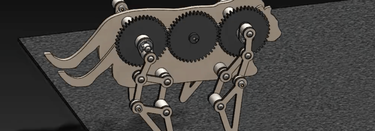
The design and assembly of our four-legged mechanical walkers can yield single degree-of-freedom systems with so many redundant mates that it stalls SolidWorks’ Motion Analysis. For example, the walker shown in Figure 1 had 782 redundant mates. The procedure outlined below reduced the number of redundant mates to 114, and Motion Analysis executed efficiently.
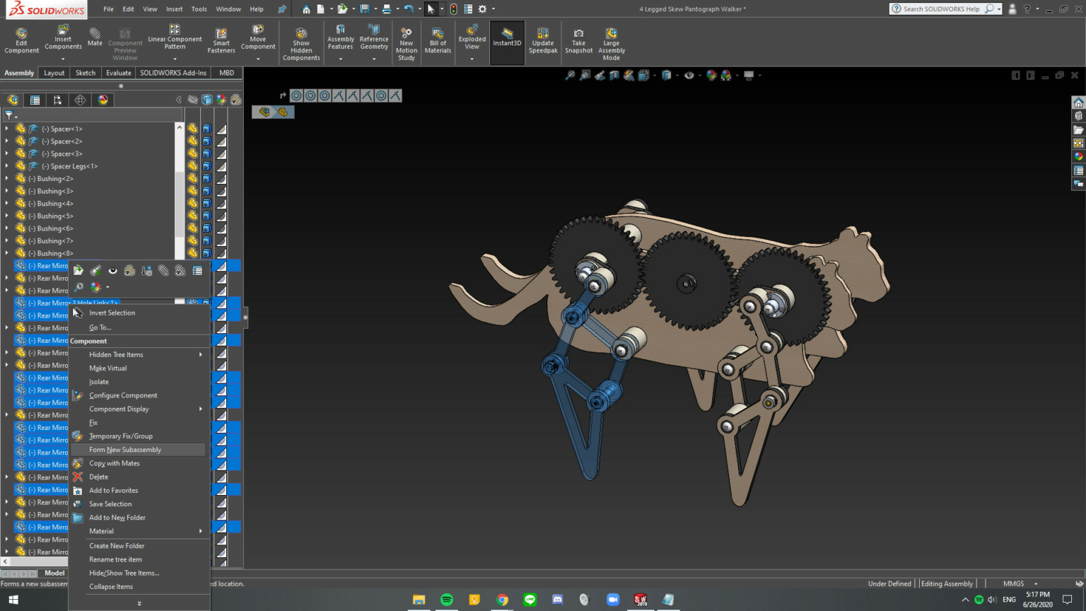
Figure 1. A four-legged mechanical walker consisting of a body, drive train, and four-leg mechanisms.
Our walker consists of a body, drive train, and four legs. The legs mechanisms are identical but assembled as front-to-back mirror images. The component parts of this walker mates were assembled using mates to align and coordinate various subassemblies, resulting in a large number of redundant mates.
In order to reduce the number of redundant mates, we dissolve the subassemblies, combine rigid elements, and mate new subassemblies as follows.
Step 1
Dissolve all of the subassemblies in the walker. To do this, hover over each assembly and select the menu item Dissolve Assembly. See Figure 1.
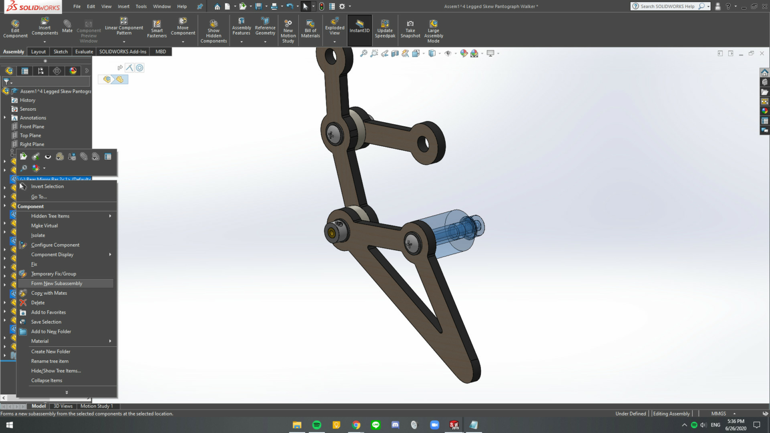
Figure 2. Selected parts for new subassembly.
Step 2
Form new subassemblies for each leg, the drive train, and the body. See Figure 2. To do this, first, hover over the part, press “tab” to hide the part in order to identify it easily; and then, select all of the hidden parts, and right-click to open menu and select Form New Subassembly.
Figure 3. Within each new subassembly form subassemblies of parts that do not move relative to each other.
Step 3
Within each new subassembly combine parts that do not move relative to each other. See Figure 3. The tree structure should consist of separate assemblies of rigid elements with the remaining mates between the assemblies. See Figure 4.
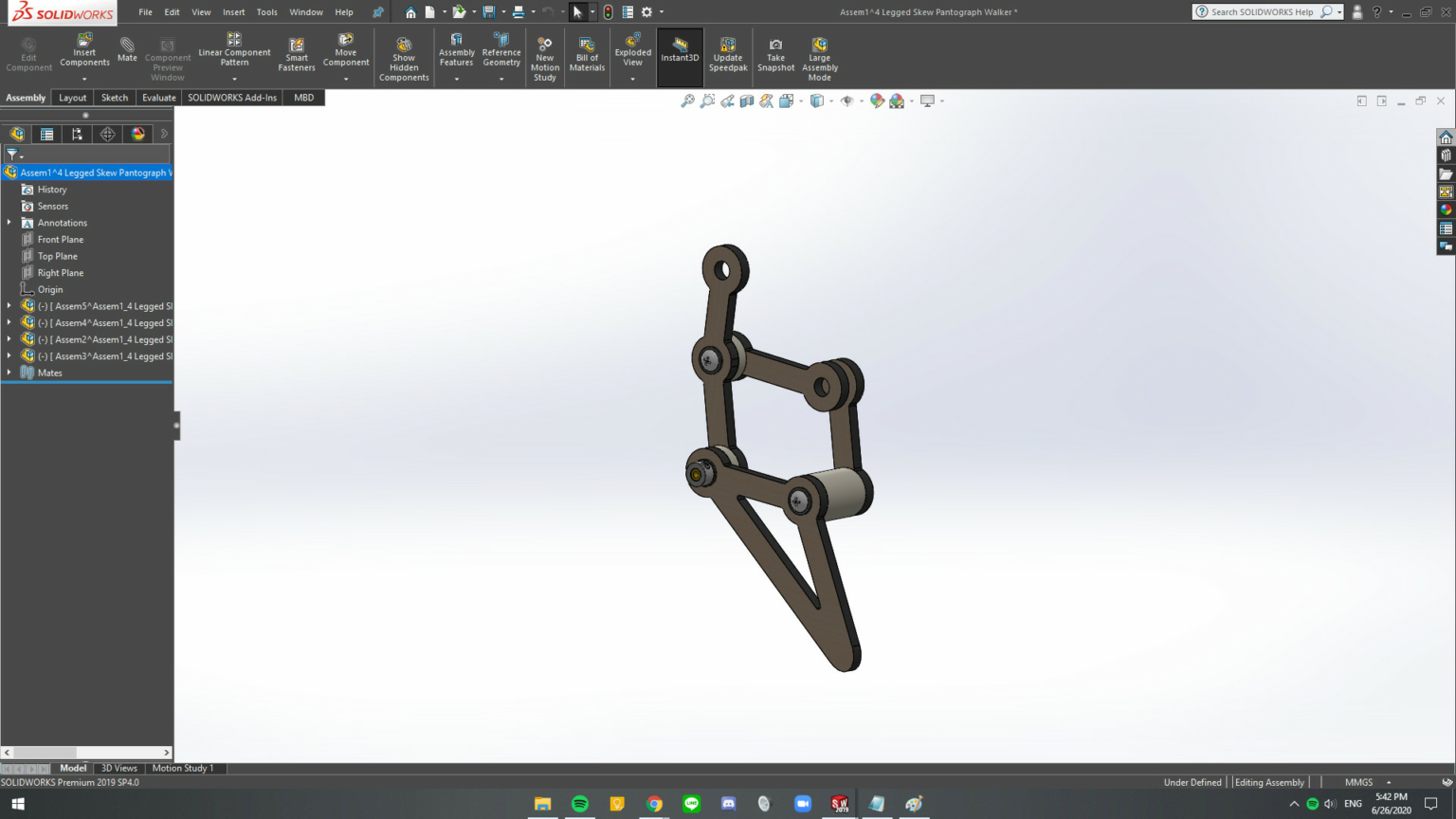
Figure 4. The assembly should consist of subassemblies that move as rigid elements relative to each other.
Step 4
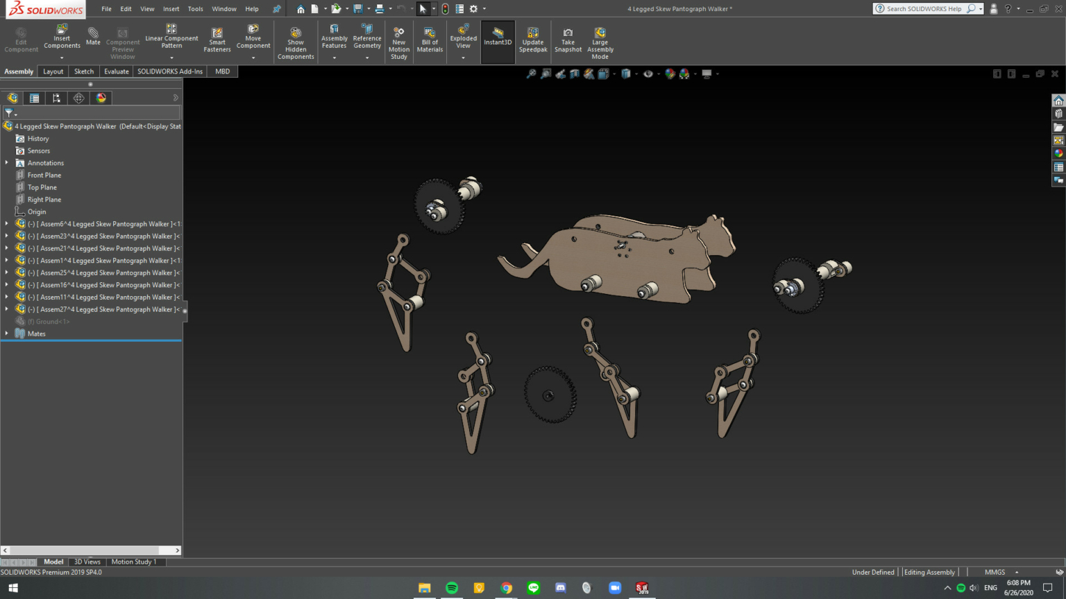
Repeat Step 3 for all of the new subassemblies. The result is shown in Figure 5.
Figure 5. The subassemblies that define the mechanical walker. Notice that the tree structure consists of subassemblies and no individual parts.
Step 5
Delete the mates in the main assembly. Introduce the mates required for movement using hinge mates, rather than coincident or concentric mates, where possible.
Step 6
Make the subassemblies at the top-level flexible. Right-click on the assembly and select the flexible assembly icon .
The result of this procedure is a system with 114 redundant mates that Motion Analysis can process effectively. The result is that animation shown below.
https://mechanicaldesign101.com/wp-content/uploads/2020/07/Screen-Shot-2020-07-19-at-5.12.37-PM.png7991600Prof. McCarthyhttps://mechanicaldesign101.com/wp-content/uploads/2016/07/mechanical-design-101LOGOf.pngProf. McCarthy2020-07-19 17:15:522020-07-19 17:39:58How to Fix SW Motion Analysis Error: Too Many Redundant Constraints

 MDA
MDA
 MDA Press